Manage
The Manage tab provides a single, common interface for managing various aspects of the software, application environment, and users. These features are only available to users with the proper administrative permissions. The following sections describe each capability in more detail.
Users
Users are created by the default “admin” user or other users who are in the Administrator's group or have create user permission. The following describes the purpose and usage of the admin user, as well as the steps to create and manage locally created users.
Default Admin User
SAINT Security Suite provides a default admin user account that has permission to all product features and content. This account is provided to perform system-level activities such as installing and configuring the product; setting up the license key; managing the update process; and performing other high-level actions such as creating users, groups, and managing permissions. Both SAINT Security Suite and SAINTCloud provide support for granular user access control and auditing user activity within the application through assigning individual users to object-based permissions. Therefore, it is recommended that the admin account for your SAINT installation (or SAINTCloud account) should not be shared by other users and used as a common login, thus eliminating the ability to track and manage individual user activity. If multiple users with full control of the system are required, those users can be added to the built-in Administrator's group. (See groups for more information about groups).
Create a User
-
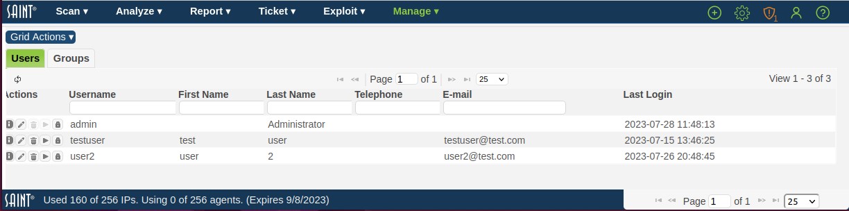
Click the Users and Groups menu option from the Manage tab to display the current list of users as shown in the following example:
-
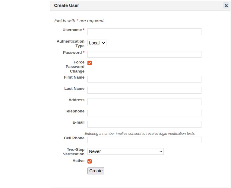
Click Create User from the Grid Actions dropdown or select User from the global (+ Create) option at the top right of the page to display the Create User page:
-
Enter a unique Username (login ID) for the new user (* required field).
-
Optional – select the Authentication type. The default authentication type, local, stores password hashes in the database, and the password is managed through the Manage-Users page. Alternatively, if Active Directory is selected, then the user will need to authenticate using his or her Windows domain password. The login name must exactly match the Windows domain login name in order for this option to work. (Note: If the Active Directory option does not appear in the drop-down menu, then the system has not yet been configured for Active Directory authentication on the Configuration screen. See Authentication.)
-
If local authentication was selected above, enter a password string for the user account. (* required field).
The user will login with these credentials. If the Force Password Change box is checked, then the user will be required to change the password after logging in for the first time. -
Optional – Enable the desired mode of two-step verification for additional security on the account. See Two-Step Verification for more information. The user’s cell phone number must be specified when using this option.
-
Click Save.
The new user account will be created. Use the grid’s refresh button to view the new user in the User display grid.
Edit a User
Once a user account has been created, you can now perform routine account updates like changing their passwords or updating their e-mail account, as well as assigning the user to groups or granting them any needed global permissions, and enter individual target hosts (by IP address, subnet, etc.) to further control access to the host environment.
-
Navigate to the Users and Groups page to display the current user list.
-
Navigate to the User or use the search and sort features to locate the user in a large list.
-
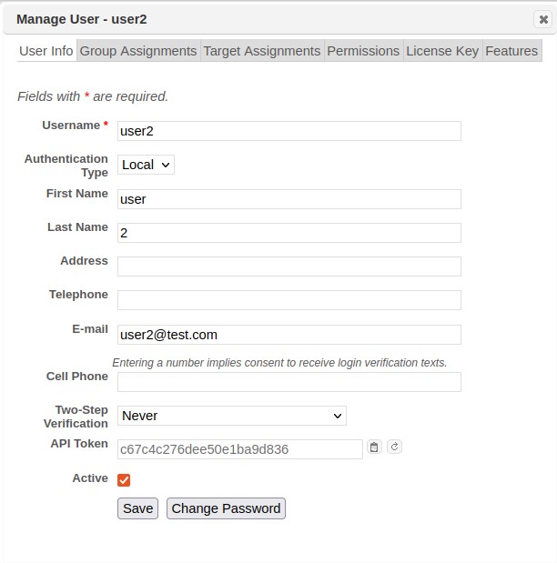
Open the Edit User dialog by selecting the user and clicking the Edit User (pencil) action on the selected row to display the user management screen, as shown below..
Edit User Information
-
Edit general information about the user from the User Info tab.
-
Click the Change Password button to expand the form field and expose the Password and Confirm New Password fields.
-
Click Save once all changes have been made.
Change Group Assignments
Groups allow you to create a set of users to whom the same permissions can be granted. (See Groups for more information). Click on the Group Assignments tab to find out which groups the user is in or to change the group assignments, as shown below:
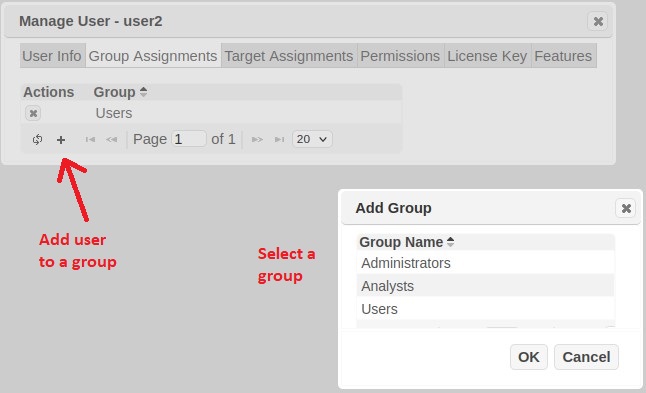
To remove the user from a group, from the Group Assignments tab, click the Remove From Group (X) icon beside the group. To add the user to a group, click the Add a Group (+) icon at the bottom of the grid, highlight the desired group, and click OK.
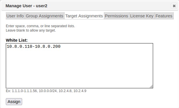
Assign Targets to Users
This tab provides the capability to grant user access to specific hosts in the target environment. Leaving this tab blank grants access to any target and leaves target management up to other security mechanisms, like Target Groups. This feature can best be described as a “white list” feature where individual target access is explicitly stated rather than implied. These decisions can be made by individual host IP addresses, space, comma or line-separated lists, target ranges, subnets, CIDR addresses, or even Domain. For example: 192.*, 1.1.1.0-1.1.1.56, 10.0.0.0/24.
-
To create the target assignments, manually enter or copy/paste the target list in the text box provided in the Target Assignments tab.
-
Click the Assign button once the list is complete.
-
The system will refresh to display the “Target Assignments Saved” message.
- Close the dialog box to return to the User management main page.
The user will now have access to the specified targets to execute actions in the system as specified by the assigned Role(s).
Assign Permissions to Users
To grant the user the ability to perform certain actions on the system, or the ability to modify specified configuration settings, click on the Permissions tab. (Note that object-based permissions, such as allowing the user to modify a target group or to view a report, are applied per object, and therefore don't appear here. See Object-based Access Controls for more information.)
Global Permissions
Global permissions give users the ability to perform certain actions system-wide. To grant a global permission, check the corresponding box and click on Save Changes.
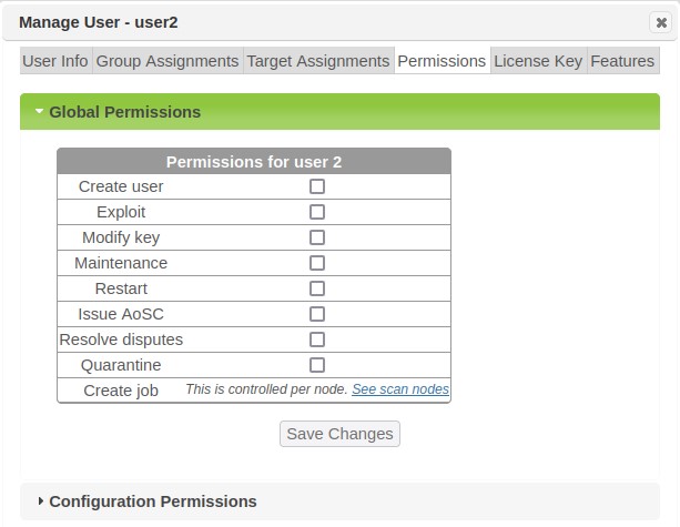
Global permissions include:
-
Create User – Allows the user to create users and groups.
-
Exploit – Allows the user to run exploits, penetration test jobs, and related actions, if the user also has the required permissions on the appropriate object, e.g., node or job.
-
Modify Key – Allows the user to configure the license key and SAINTexpress plug-in.
-
Maintenance – Allows the user to perform the system functions found on the System Maintenance screen, including taking backups and viewing logs.
-
Restart – Allows the user to restart the system. On appliances, it also allows the user to shut down or restart the appliance.
-
Issue AoSC – Allows the user to approve or deny requests for Attestations of Scan Compliance. (See PCI Attestations.) Only users who are certified ASV employees should have this permission. (This permission is only used if Attestation of Scan Compliance is enabled in the license.)
-
Resolve disputes – Allows the user to approve, deny, or request more information for a dispute. (See Resolve a Dispute.) If the dispute feature is being used in conjunction with ASV scanning, only users who are certified ASV employees should have this permission.
-
Quarantine – Allows a user to view the Quarantine asset action option for vulnerability results in the Analyze tab, and choose to send a quarantine message to Cisco Identity Service Engine (ISE). Note that this action option and communication is only supported for Security Suite installations pre-configured (Security Configuration options and Cisco ISE integration configurations) to provide for security communication between the two products.
-
Create Job – Allows the user to create scan jobs for scanner Nodes the user has permissions to. Selecting this option will transfer you to the Manage Nodes page to setup scan permission for the applicable scanner(s).
Configuration Permissions
Click on the Configuration Permissions bar to expand the Configuration Permissions panel. These permissions allow a user to modify the values contained in the corresponding configuration setting categories, either globally or per scan. If the checkbox in the “modify globally” column is checked, then the user is allowed to change the global default values, which will be applied in every scan job for which the corresponding setting hasn’t been overridden. (See Configuration.) If a checkbox exists in the “override per scan” column and it is checked, then the user is allowed to override the default values when creating scan jobs. (See Advanced – Step 4.) The bold categories are top-level categories which include the categories below it. Click on Save Changes at the bottom of the panel to save your changes.
Assign Features to Users
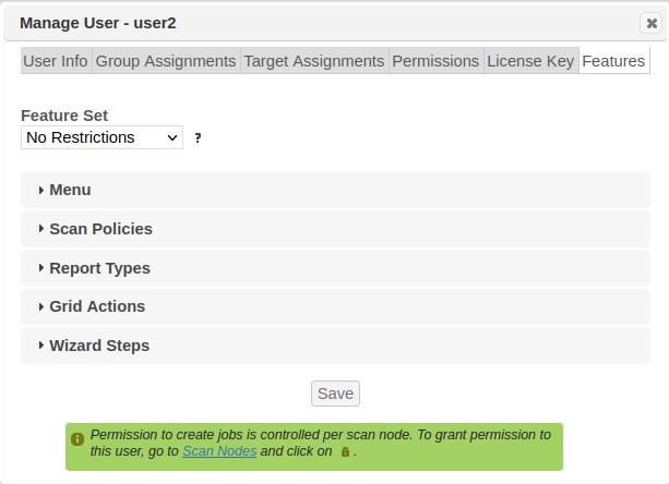
To specify which screens, functions, and options in the web interface are available to the user, click on the Features tab. This allows you to choose a feature set which is appropriate for the user. You can choose one of the pre-defined feature sets or define a custom feature set.
Note that the feature set is intended to simplify the user experience by hiding unused options, not to be an access control feature. The feature set only affects the user’s web session, not the API. To properly prevent users from gaining unauthorized access to manager objects, use SAINT’s access control features instead of a feature set. See Access Controls and Assign Permissions to Users for more information.
Feature selections do not override permissions or license restrictions. That is, checking a feature only shows the feature if the user has permission and the feature is licensed.
Pre-defined Feature Sets
The pre-defined feature sets are as follows:
-
No restrictions – Every available feature is enabled for the user. This is the default for newly created users and groups. Note that some features may still be restricted by your license key even if they’re enabled in the feature set.
-
Common features – Only commonly used features are enabled for the user.
-
Reporting only – Only analytics and reporting screens are available for the user.
-
ASV customer – This feature set enables only the features which are part of the PCI ASV attestation workflow, such as the PCI External scan policy, attestation requests, and disputes.
To choose one of the pre-defined feature sets, select it from the drop-down menu and click on the Save button.
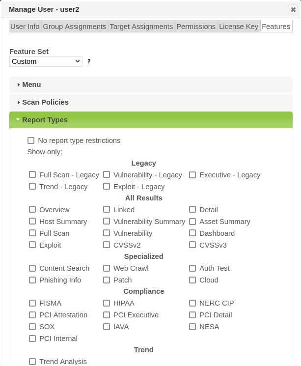
Custom Feature Sets
If none of the pre-defined feature sets are appropriate for the user, you can create a custom feature set by enabling or disabling individual features. The individual features are organized into five feature groups:
-
Menu – Which options the user sees on the top menu bar.
-
Scan Policies – Which scan policies the user can choose in the scan wizard.
-
Report Types – Which report types the user can choose in the report wizard.
-
Grid Actions – Which options the user sees in various Grid Actions menus, and which action buttons the user sees on each row of various grids.
-
Wizard Steps – Which steps, field sets, and options the user sees in the scan wizard.
To create a custom feature set:
-
Optional. Choose one of the pre-defined feature sets to use as a starting point.
-
Expand any of the feature groups.
-
To enable all features in the feature group, check the no restrictions box. To enable only certain features in the feature group, uncheck the no restrictions box and check the desired features. (Unchecking all boxes is equivalent to checking the no restrictions box.)
-
Repeat steps 2-3 as desired for other feature groups.
-
Click on the Save button.
Feature Priority
In cases where a user and their group(s) have a different feature set, restricted sets in a given feature group take priority over unrestricted sets in the same group. For example, if a user has “no menu restrictions” checked but the user’s group has some menu options selected, the user will see only the selected menu options. If a user has the default “no restrictions” feature set but the user’s group has the “common features” feature set, then the user will have the “common features” feature set.
If the user and group both have restricted feature sets, then the feature sets are merged. For example, if a user has the “Scan Jobs” menu option enabled, and the user’s group has the “Reports” menu option enabled, then the user will see both the “Scan Jobs” and “Reports” menu options.
Groups
A group is a set of users to which permissions can be granted as a single unit. There are several benefits to using groups. Firstly, granting permission to a group only involves a single step, whereas granting the same permission to multiple users individually involves more effort. Secondly, groups allow new users, or users who change job functions, to be granted an existing set of permissions simply by adding the user to an existing group which already has the appropriate permissions for that user’s job function.
Built-in Groups
Even before you create any groups, there are three default groups:
-
Administrators group – This is a special group which gives all of its members full control of the entire system and all objects. This group allows there to be multiple administrators without requiring all of them to share the one built-in admin user.
-
Users group – All users are automatically assigned to this group when they are created (unless the user was created by a non-administrator who was not a member of this group). This provides a convenient way to share objects (such as reports) with all users if desired.
-
Analysts group – This group gives its members view access to all scan results in the system, but nothing more. This group is useful for easily allowing a user to perform analytics and reporting, without allowing the user to create jobs or run scans. The Scan tab on the top-level menu bar is hidden from users in this group.
Create a Group
-
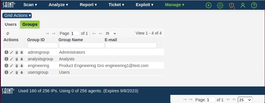
Click the Groups menu option from the Users and Group tab to display the current list of groups as shown in the following example:
-
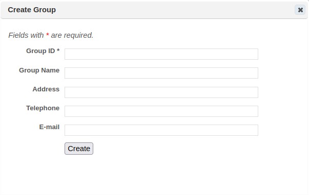
Click the New Group (+) option at the bottom of the grid to display the Create Group page:
-
Enter a unique Group ID and Group Name.
-
Use the remaining fields to enter any other information you wish to store to identify the group.
-
Click Save.
Edit a Group
Once a group has been created, you can change the group’s information or add members to the group as follows:
-
Click the Groups tab in the Users and Groups page to display the current group list.
-
Navigate to the desired group, or use the grid’s search and sort features to locate the group in a large list.
-
Open the Edit Group dialog by selecting the row and clicking on the pencil icon on the row or at the bottom of the grid.
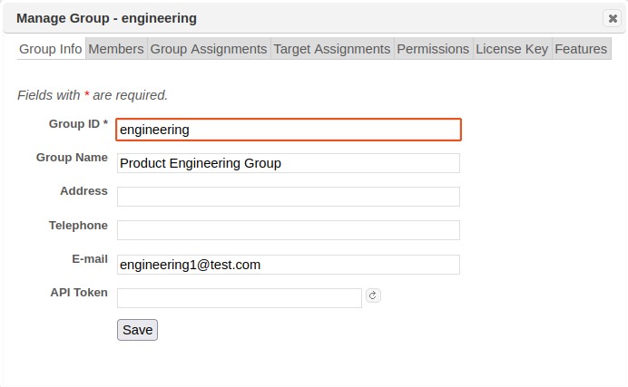
The Group Info tab can be used to edit the group’s name and identifying information. The Permissions tab can be used to edit the group’s global permissions and configuration setting permissions. (See Assign Permissions to Users for more information). The Target Assignments tab can be used to assign target ranges which group members are allowed to scan. (See Assign Targets to Users for more information).The Features tab can be used to define a feature set for the group. (See Assign Features to Users for more information.)
Note that groups can be members of other groups. In that case, members of that group inherit not only the permissions of that group, but also the permissions of any groups of which that group is a member. This allows creation of groups in a multi-level hierarchy. The Group Assignments tab can be used to add the group to other groups. (See Change Group Assignments for more information.)
User Groups can also have their own License Key. This license key design can be optimal for organizations that have disparate operating budgets, license type requirements (metered versus per IP), or for managed service organizations that license the product for multi-tenant deployments.
Adding Members to a Group
To add members to a group, click on the Members tab, and then click on the Add a Member (+) icon at the bottom of the grid. Use the paging buttons, sort buttons, and search boxes to locate the desired users and groups if necessary, and check the box beside those users and groups. Then click OK.
Note: members can also be added to or removed from groups by editing the member rather than editing the group. See Change Group Assignments for more information.
Removing Members from a Group
To remove members from a group, click on the Members tab; locate the users and groups to be removed, and either click on the Remove From Group (X) icon on each row you wish to remove, or select multiple rows and then click the Remove From Group (X) icon at the bottom of the grid to remove multiple members at once. Click OK at the prompt to confirm.
Assets
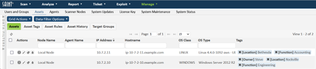
The capabilities in the asset management module enable users to view, search, sort, tag, assess and report on hosts scanned by SAINT’s scanner(s). As shown below, asset management is segregated into three main collections of data: Assets; Asset Tags; and Target Groups.

You can sort this list, perform column searches, see detailed information about a record in the display, or take other actions such as adding/removing columns, refreshing the display to dynamically update the content with any new content since you entered the grid, and take other actions related to creating, editing, and deleting content. The following describes these features in more detail.
Assets included in this data grid represent hosts that have been discovered and/or assessed by the scanning engine. By default, post scan processes create system tags for the following system-provided Tag Names:
-
Asset ID – unique ID stored in the database for the asset
-
Node – this value is the SAINT scanner that identified the asset. For single scanner environments, this is typically the “Local Node”. For Multi-scanner environments, this value will be the Local Node or one of the distributed scanners connected to the central Manager.
-
IP Address – IP address (supports both IPv4 and IPv6)
-
CPE – Common Platform Enumerator
-
Host Name – if collected by any scan associated with this asset
-
MAC Address – if collected by any scan associated with this asset
-
NetBios Name – if collected by any scan associated with this asset
-
OS Type – Operating System and Version (example: Windows 7 SP1)
-
OS Class – Operating System vendor classification (examples: Windows; Red Hat)
AWS Asset Tagging – If the SAINT Agent is installed on an AWS asset, then its metadata will be collected and stored as asset tags. This data includes aws-vpc, aws-subnet, aws-size, aws-id, and aws-zone.
Edit Assets
Certain information about the assets is intended to be edited by the user, such as the asset's criticality, whether it stores sensitive data, and whether it is an Internet facing asset. These properties are among the risk factors used to calculate risk scores for the asset's vulnerabilities. To edit this information, click on the Edit Asset button (pencil icon) in the Action column of the grid. Alternatively, select one or more assets and then choose Edit Assets from the Grid Actions menu. This will open a dialog box:
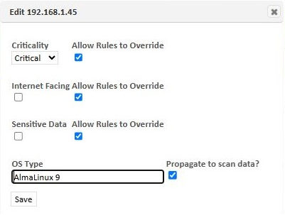
To change the properties of the selected asset(s), change them on this form and click Save. For the criticality, internet facing, and sensitive data properties, there is also a checkbox labeled Allow Rules to Override. This box is checked by default, allowing asset rules to change the value of the property. (See Asset Rules) Uncheck the box if you want to lock the value of the property, so it won't be modified by rules. The asset's OS type can only be edited if it was determined by a network-based scan. When editing the OS type, checking the Propogate to Scan Data box will change the OS type in the scan data in addition to the assets grid.
Add Asset Tags to Assets
Scanned hosts stored in the database can be ‘tagged’ with descriptive values to enhance the effectiveness of viewing, analyzing, assessing and managing these hosts as business assets. Asset Tags are based on a Key-Value pair concept. For example, each tag will have both a Key (example: Location) and at least one Value (example: Dallas). The following are examples to better illustrate this concept:
-
Criticality=High
-
Criticality=Medium
-
Criticality=Low
-
Location=Data Center
-
Location=Home Office
-
Function=Accounting
-
Function=Shopping Cart
-
Function=Email Server
-
System Owner=John Smith
-
Business Cost=$20,000,000
Tag a Single Asset
The following example illustrates how a single asset can be tagged with pre-existing asset tags or creating new one’s dynamically as they are being associated with the asset:
-
Navigate to the Assets tab under the Assets page in the Manage menu.
-
Click on the Edit Tags action button for the asset to be tagged.
An Asset Tag Assignment dialog will be displayed, as shown in this example. This dialog will display existing Tag Names and Values (example: IP Address=10.8.39.188), and the Data Type associated with the tag (default: String) as well as a few blank rows to dynamically apply other existing tags or create and tag the asset with new tags without having to navigate to the Asset Tags data grid and create them first. Note that some asset tags (for example: Node, Hostname, ID Address, OS Class and OS Type) are generated by the scanner when they are scanned and are “read only.”
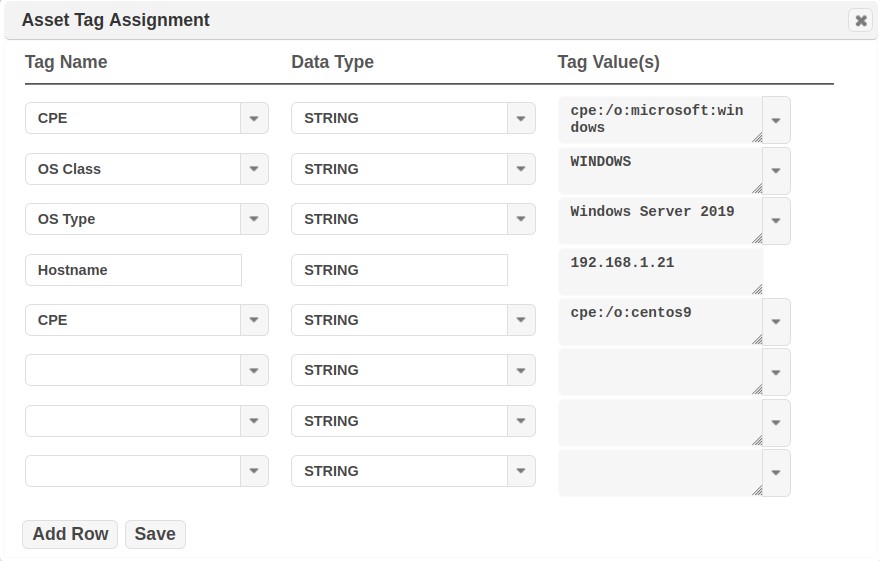
Apply an existing Tag:
I. Select a Tag Name in a blank Tag Name drop-down menu. (Example: Location)
II. Select a Tag Value in the Tag Value(s) drop down menu for this Tag Name. (Example: Baltimore)
To create a new Tag Name and Value and apply it to the Asset:
I. Enter the Tag Name directly in a blank row under the Tag Name. (Example: Owner)
II. Select the Data Type applicable to the tag. (default: String)
III. Enter a Tag Value to be associated with the Tag. (Example: SOC)
Remove a Tag:
I. Click on the down arrow for the Tag Name or Tag Value that you wish to remove.
II. Select the blank row in the drop down menu list.
-
Save the change to tag the asset and new tags into the Asset Tag table.
-
Close the assignment dialog to see:
Tag Multiple Assets from a Single Operation
Adding Tags in Bulk
Multiple assets can be tagged through a single operation by clicking the Asset grid's Grid Actions > Assign Asset Tags option. The following describes how to apply tags in bulk through this operation:
-
Navigate to the Assets tab on the Assets page.
-
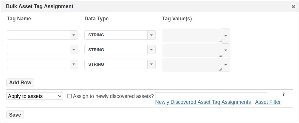
Click on the Grid Actions > Assign Asset Tags option. The following Bulk Asset Tag Assignment dialog will be displayed:
-
First, select the Tag Name(s) and Tag Value(s) you wish to assign to the collection of assets. This can be done by clicking on each Tag Name and Tag Value drop-down lists to select existing Tags; or by manually entering new Tag Name(s) or Tag Value(s) directly in-line in a blank row, if the required tag has not yet been created.
-
Ensure the “Apply to” action is shown in the cell above the Save button.
-
Enter the asset information in the Assets field to identify assets to be tagged.
i. Use the Help (?) option to the right of the Assets field for assistance on acceptable identifiers, to include, but not limited to: IP, Hostnames, IP ranges, CIDR blocks, Subnets, etc.
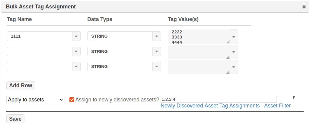
ii. Use the “Open Asset Filter” option to select existing assets based on system-defined and custom tags. In the following example, we will use this feature to identify three hosts, by IP address, that we wish to tag as being owned by the Security Operations Center (SOC). Click OK to add the assets and close this dialog.
iii. There is an option to assign asset tags to newly discovered assets. This means that any time a new asset is discovered which meets the criteria (set by using the input field to the right of the checkbox), the asset tags will automatically be applied to it.
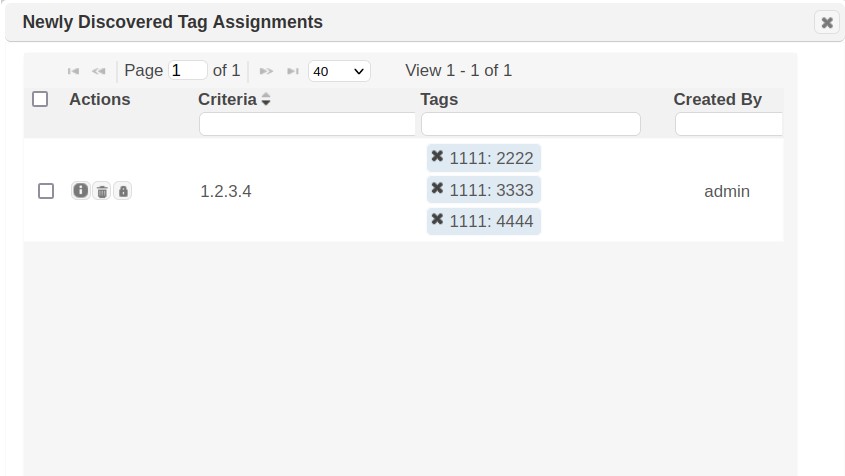
iv. Clicking on the “Newly Discovered Asset Tag Assignments” link will bring up a grid showing all the assignments that have been saved, as shown below.
From this grid, the newly discovered asset tag settings can be viewed and removed. Removing a tag from this grid will not remove the asset tag from the database, but only remove it from being automatically assigned to the targets specified in the criteria.
-
Verify the Asset list and Tag Assignment values and Click OK to assign all tags to the collection of assets.
-
Close the dialog and view the resulting tags in the Assets table.
These tags will now be applied to the asset and available for tracking for existing and future scan results.
Removing Tags in Bulk
Just as tags can be assigned in this bulk assignment process, they can also be removed in the same manner. Use the steps defined in the Adding Tags in Bulk section, except you will change “Apply to” to “Remove from” in Step four. This operation will use the Tag and Asset criteria defined in the Bulk Asset Tag Assignment dialog to execute the task in a single operation, as opposed to manually removing tags individually at the Asset row level by clicking on each Asset Tag’s X (delete) option.
Asset Sources
Asset sources can be used to retrieve assets from an external source such as Active Directory, add them to the SAINT asset repository, automatically create asset tags based on the attributes collected, perform asset source and unique identifier-based scans, and establish connectivity for change management. This feature can be found by going to the Manage -> Assets page. (This feature is only available to customers who have Asset Import enabled in their license.)

Creating and Editing Asset Sources
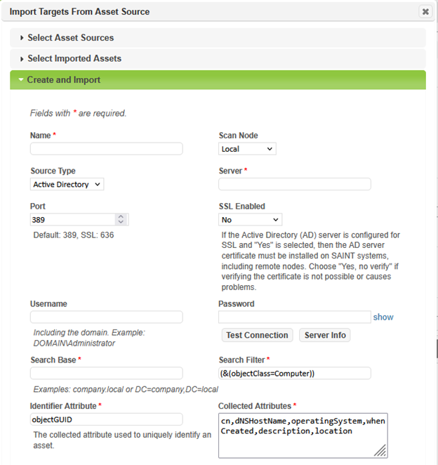
To create an asset source, click on Grid Actions -> Create Asset Source. To edit an asset source, click on the pencil icon next to the asset source. This will load the dialog in the following screenshot:

Asset Source Options
Scan Node – This is the scan node that has visibility to the asset source server. The asset source server will be queried from this node.
Search Filter – This should be a valid asset source search filter string. For Active Directory, see https://learn.microsoft.com/en-us/windows/win32/adsi/search-filter-syntax.
Identifier Attribute – The attribute defined by the asset source schema used to uniquely identify an asset. The default active directory attribute is objectGUID.
Collected Attributes – These are the attributes to be collected from the asset source server. Asset tags will be created from these fields automatically during import.
Background Imports – To enable periodic imports, specify an hour value in this field. To disable automatic imports, set this field to 0. This can be changed at any time. Background imports will occur once every N hours after the last import.
Match Existing Assets by – If enabled, when new assets are imported, SAINT will try to match assets to an existing SAINT asset record based on the selected option. The options are hostname, scan node + hostname, or scan node + computer/netbios name (CN).
Resolve Hosts – If enabled, when new assets are imported, SAINT will attempt to resolve hostnames to an IP address for use in SAINT’s asset repository.
Connectivity Test
To test the connectivity and authentication to an asset source, fill in the following fields and then use the Test Connection button:
- Scan Node
- Server
- Port
- SSL Enabled
- Username
- Password
If the connection is successful, you will see a “success” message appear next to the button. Otherwise, an error message will be displayed.
Server Info
The Server Info button can be used to help determine a search base as well as what the asset source server permits and authentication mechanisms. To use this feature, the following fields need to be filled in: Server.
Importing Assets
There are three options for importing assets.
- Manual – Use the Import Assets button (down arrow icon) next to an asset in the asset sources grid. If credentials have not been saved, an input prompt will be displayed:

- Manual Bulk – Use the Import Assets option from the Grid Actions pulldown menu. Credentials need to be pre-set to use this option.
- Background – Assets will run once every N hours determined by the Background Imports setting.
Imported assets will have several new fields available in the assets grid.
- Asset Source - The name of the asset source the asset was most recently imported from.
- Asset Source GUID - The asset's unique identifier as defined by the asset source server.
- Created At - The date the asset was first imported.
The Assets grid now has a new field called Last Scanned which indicates the last time an asset was scanned.
Deleting Asset Sources
To delete an asset source, use either the trashcan icon in the Asset Sources grid, or the Delete Asset Source(s) option from the Grid Actions pulldown menu. Asset source tags will remain in place, however scans using a deleted asset source will no longer be able to resolve to their current hostname/IP at scan time.
Asset Source Scanning
The unique identifiers and asset tags can be used to scan assets that have been imported from an asset source. Targets will be resolved to their hostname and IP address by using an LDAP query at scan time.
Scan by Asset Source
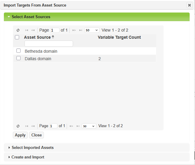
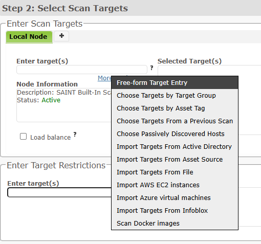
To scan by an asset source, in step 2 – Targets of the scan wizard, click on More Options… From here you can select Import Targets From Asset Source. Expand Select Asset Sources and select the asset source to scan. This will scan all assets that are attached to the selected asset source each time the scan starts. The target list does not need to be updated if new assets are imported after the job has been created.
Scan by Asset Source Unique ID
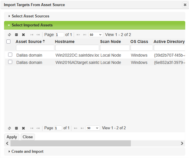
To choose individual targets that have been imported by an asset source, or to create and import a new asset source during target selection, click on More Options… and choose Import Targets from Asset Source.
Asset Source History
If an attribute such as IP address or hostname have changed during an asset import, then an asset history record will be created in the Asset History grid.

Asset Tags
The Asset Tag data grid, as shown below, provides a complete list of all tags in the system, as well as a count of the total number of assets currently tagged with each value.

Add Asset Tag
New asset tags can be created by navigating to Grid Actions > Create Asset Tag option from the Asset Tags tab to display the Asset Tags creation form:.
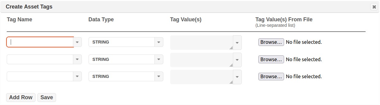
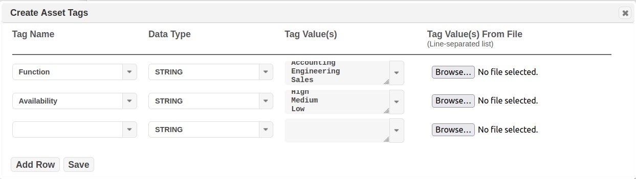
As shown in the dialog, you can add a completed new 'Tag Name-Tag Value' combination, or you can select an existing Tag Name and add additional values to it. The following example includes adding a New Tag Name: Function, as a Data Type=String, and add 3 values, as well as adding a Tag for Business Availability. Note this can be done directly “in line” in each cell (as shown in these examples) OR you can upload a text file with the values listed in a line separated list. A text file list can save a lot of time, for example, if you have hundreds of values, as in the case of asset owners or locations.
-
Click Add Row if you wish to add additional tags before saving.
-
Click Save to save your tags.
-
Close the dialog window to view the new Asset Tags.
Edit Asset Tag
-
Navigate to the Asset Tags tab under Manage Assets.
-
Click on the Edit (pencil) action button on an Asset Tag.
-
You will have the option to edit the Tag Name or Tag Value for the selected tag.
-
Edit the Name(s) and Tag Value(s) as needed.
-
Click Save.
-
Close the dialog window to save your changes.
Delete Asset Tag
A user can choose to delete the entire Name-Value collection by choosing to delete a Tag Name or choose to delete just the record associated with a Tag Name’s Value.
-
Navigate to the Asset Tags tab under Assets.
-
Click on the Delete (trash can) action button on an Asset Tag.
-
You will have the option to Delete the Tag Name or Tag Value for the selected tag.
-
The system will display a message to confirm the delete action.
-
Click OK to accept and delete the selected tag. Click Cancel to exit the process and retain the tag.
Note: Deleting an asset tag does not impact current or future scan results. However, tag values will be removed from reference to any associated scan Jobs or results. For example, if a previous scan contained assets associated with Location=Dallas and the Location tag is removed, then scan results will no longer be associated with this location. Also, if a Scan Job was configured based on the tag that is being deleted, then that Job will no longer be associated with a Tag or their associated assets. Those jobs will need to be edited, as needed, if the intent is to reuse/re-run them in the future. A recommended BEST PRACTICE is to retain Asset Tags (not delete them) once they have been associated with scan Jobs and scan Results, unless the tags, jobs and results have no future value. This will ensure existing Jobs work as configured and any scan results continue to be associated with the tag(s), even if they are historic in nature.
Asset Rules
Note: the features described in this section are only available to customers who have the SAINT VRM module enabled in their license key.
Asset Rules allow you to automatically set risk factors and tags on scanned assets based on the scan policy, IP address, or scan findings. Each rule may set one or more of the following:
- Criticality: How critical is the asset to the organization? (Default: Medium)
- Internet Facing: Is the asset publicly available over the Internet? (Default: Yes)
- Sensitive Data: Does the asset store or expose Personal Identifiable Information (PII)? (Default: No)
- Asset Tags: List of key-value pairs which can be used for selecting targets or filtering results.
Rule sets are applied at scan time if selected in the job (see Create New Job), or can be applied on demand to existing assets. When the rule set is applied, asset tags will be assigned from all matching rules, and each risk factor will be set from the first matching rule which sets that risk factor.
To create, modify, delete, or appy rule sets, choose Manage -> Assets from the top menu and choose the Asset Rules tab.
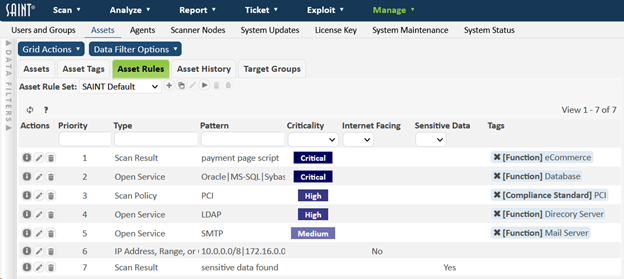
Default Asset Rule Set
SAINT Security Suite has one built-in asset rule set called SAINT Default. This is designed to be a general rule set which sets the risk factors and some asset tags based on common scan findings. It is available to all users and cannot be modified. If you try to modify it, you’ll be prompted to copy it to a new rule set.
Create Asset Rule Set
To create a new asset rule set, click on the Create Rule Set (plus icon) button beside the Asset Rule Set drop-down menu. This will prompt you to enter a name for your custom rule set, and then it will create an empty rule set. If you’d rather initialize your custom rule set using an existing rule set, select the rule set from the Asset Rule Set drop-down menu, and then click on the Copy Rule Set button and enter a name for the rule set.
Delete Asset Rule Set
To delete an asset rule set, select the rule set from the Asset Rule Set drop-down menu, and then click on the Delete Rule Set (trash can icon) button beside the drop-down menu. Note that the SAINT Default rule set cannot be deleted.
Apply Asset Rule Set
Asset rule sets can be applied either during scan processing or on demand. To apply a rule set during scan processing, select the rule set when creating or editing the scan job. (See Create New Job)
There are two ways to apply a rule set on demand. The first way is to select the rule set from the Asset Rule Set drop-down menu, and then click the Apply Rule Set (triangle icon) button. Then click the Apply button in the resulting dialog. This will apply the asset rule set to all existing assets to which the logged-in user has permission, which could take several minutes. You can click on the Cancel button at any time to stop applying the rule set.
The second way to apply a rule set on demand is from the Assets tab. Optionally, select one or more assets. Then choose Apply Asset Rules from the Grid Actions menu. This will open a dialog allowing you to select the asset rule set to apply, and the assets it will be applied to. Click Apply to begin applying the rule set.
Create Asset Rule
To create an asset rule, choose Create Asset Rule from the Grid Actions menu. This will open a dialog allowing you to create an asset rule. (If the SAINT Default rule set is selected, you will first be prompted to enter a name for the modified rule set.). Set the fields of the asset rules as follows:
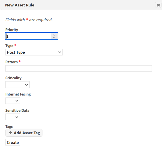
- Priority – the rule will be inserted into the rule set at this priority level. Lower numbers have higher priority. In the event that more than one rule matches an asset and tries to set the same risk factor, the rule with the lower number will take priority.
- Type – the asset, scan, or result information in which to look for the match condition when the rule is applied.
- Pattern – the match condition for the selected information type. The rule will be considered a positive match if this string appears in the information type selected above. The string is case-insensitive, and multiple patterns can be specified as a pipe-separated list for a logical or.
- Criticality, Internet facing, Sensitive data – risk factors to set on the asset in the event of a positive match. Each of these fields is optional, but at least one of them or an asset tag must be specified for each rule. If any of these fields are not set, the corresponding value on the asset will remain unchanged in the event of a positive match.
- Tags – the asset tags to add to the asset in the event of a positive match. Click on the Add Asset Tag button to add or modify tags. Click on the X on any existing asset tag to delete the tag. (This can also be done directly on the Asset Rules grid.) Note that this only removes the asset tag from the rule, and not from assets to which the rule has already been applied.
View Asset Rule
To view an asset rule, click on the Details (i icon) button in the Actions column of the Asset Rules grid. This will display all available information about the rule.
Edit Asset Rule
To edit an asset rule, click on the Edit (pencil icon) button in the Actions column of the Asset Rules grid. This will open a dialog allowing you to edit the asset rule. (If the SAINT Default rule set is selected, you will first be prompted to enter a name for the modified rule set.)
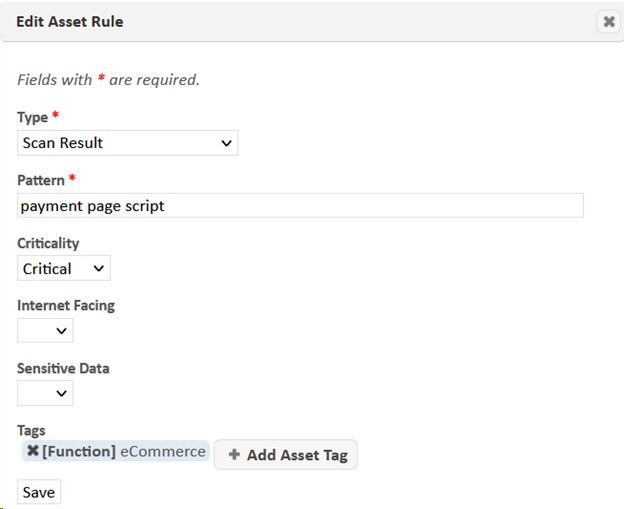
See Create Asset Rule above for a description of each of the inputs in this dialog.
Delete Asset Rule
To delete an asset rule, click on the Delete (trash can icon) button in the Actions column of the Asset Rules grid. The rule will be deleted, and the priority of the rules below it will be decremented to close the gap.
Reorder Asset Rules
To reorder the rules in an asset rule set, click on a rule and drag the rule up or down to the desired position while holding the mouse button. The priority values of the rules between the old and new positions will be renumbered accordingly. Lower numbered rules take priority if more than one rule matches an asset and tries to set the same risk factor. Note that reordering rules is only possible when the rule set is unfiltered.
Agent History
SAINT Agents allow us to track what has changed on the asset, such as its IP, hostname, MAC address, etc.
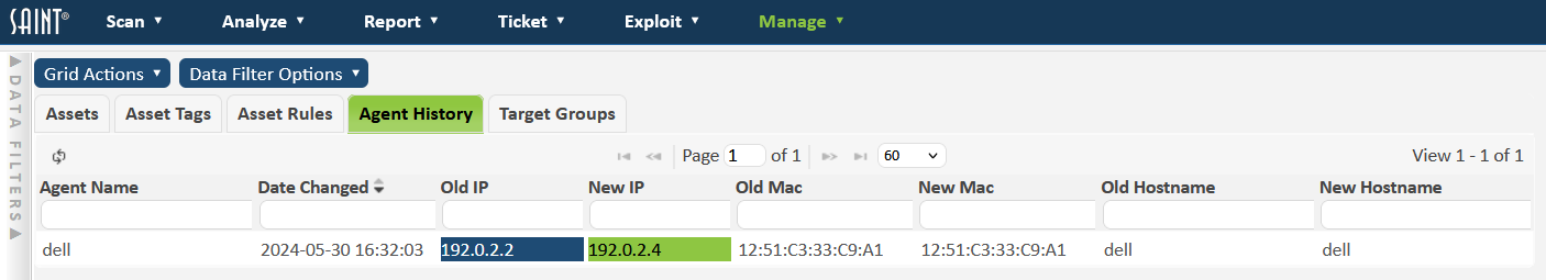
To view all agent history, navigate to Manage > Assets and click on the Agent History tab. When a change occurs, the time is noted in the Date Changed column. The old value is highlighted in blue and the new in green. Unchanged fields are left in white. To view the history of a single asset, use the filter tool bar at the top of each column, or go to Manage > Agents and use the history button in the Actions column.
Agents
SAINT Agent Overview
Note: The features described in this section require Agents to be enabled in your license key, and the Agent Server to be enabled in the System Options.
The SAINT Agent is a client-side service which is used to assess a system and report vulnerabilities, configuration issues, and information back to SAINT Security Suite. The collected data can then be analyzed and used within the application the same way it would be when performing remote scans. Some of the benefits of the SAINT Agent are:
-
No credential management or authentication issues
-
Asset tracking
-
Targets can be scanned the moment they connect within a given assessment duration
The SAINT Agent is currently supported on the following operating systems:
-
Windows 10+
-
*Mac OS X 12+
-
*Ubuntu 16.04+
-
*Debian 7+
-
*Red Hat 7+
-
*CentOS 7+
-
Amazon 1 and 2
-
Rocky Linux 8+
-
AlmaLinux 8+
* Python 3 is required to work on Linux and MacOS.
Managing Agents
From the Manage -> Agents tab, SAINT Agents can be monitored, configured, and troubleshooted. This is also where SAINT Agent installers are available for download.
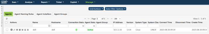
The agents grid will display all scan agents that have connected to the server at least once. The grid displays information about assets such as their SAINT Agent name, hostname, IP, external IP, system type, as well as each Agent's connection status and registration status.
The following actions are available from the grid’s Actions column.
-
View – Lists all the information associated with the Agent.
-
Edit – Allows you to change the name, registration status, and attach a comment to the Agent.
-
History – Brings up a list of everything that has changed on the system such as the IP, hostname, MAC address, etc.
-
Log – If connected, the scanning and update log from the Agent can be downloaded.
-
Remote Configure – From here, the remote logging level and max processes can be set on the Agent. This can be done in bulk from the Grid Actions menu as well. Agents do not have to be connected when these are set -- they will be set the next time a connection is made.
-
Uninstall - The trashcan button can be used to uninstall individual agents. Multiple selected agents can be uninstalled by using the Grid Actions ->Uninstall Agents link. Agents that are uninstalled will change to disconnected and have a status of "Retired". If you need to reinstall an agent, you will need to edit the "Retired" agent by using the pencil button and setting its status to "Active" before reinstalling. Agents that are offline at the time of uninstallation will be uninstalled the next time they connect.
-
Permissions – Control who has access to the Agent.
Agent Naming Rules
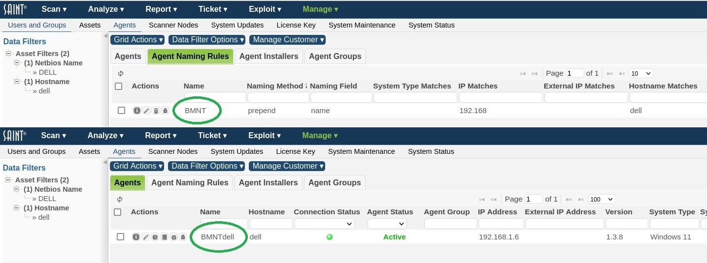
Agents are named using their hostname by default. Rules can be specified to change this behavior. Rules are created by using assignment criteria such as IP, hostname, system type, and asset tags. By clicking on Apply All Naming Rules from the Grid Actions dropdown, each rule is applied to matching agents based on the application method:
-
Overwrite: Hostname is overwritten with the given agent name and a unique #N suffix.
-
Prepend: hostname is prepended with the given agent name.
-
Append: hostname is appended with the given agent name.
The default names can be restored by clicking on Reset Agent Names to Hostname from the Grid Actions dropdown.
Agent Installers
The Agent Installers tab contains the various installers for different platforms. Note that it is important to download the installer with the correct architecture for Windows, as installing the 32-bit version on a 64-bit machine will cause certain checks to run improperly.
Agent Groups and Permissions
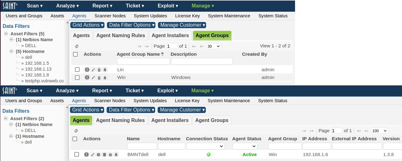
Agent groups can be used to specify the location which an agent resides. This field is configurable at agent installation time and may also be set through the GUI after an agent connects. For example, if you have a set of agents at client A and client B, this field could be used to distinguish them and make searching much easier.
Agent groups also make permission handling much easier. All permissions assigned to a given agent group, also apply to all the agents in that group.
Agent Registration
The number of agents currently registered can be found at the bottom of the UI.


The usage can be decreased by using the edit button and setting the Agent to Retired. Agents can be unretired by using the edit button and setting the Agent to Active. Only agents that are in the Active state can connect and perform scans.
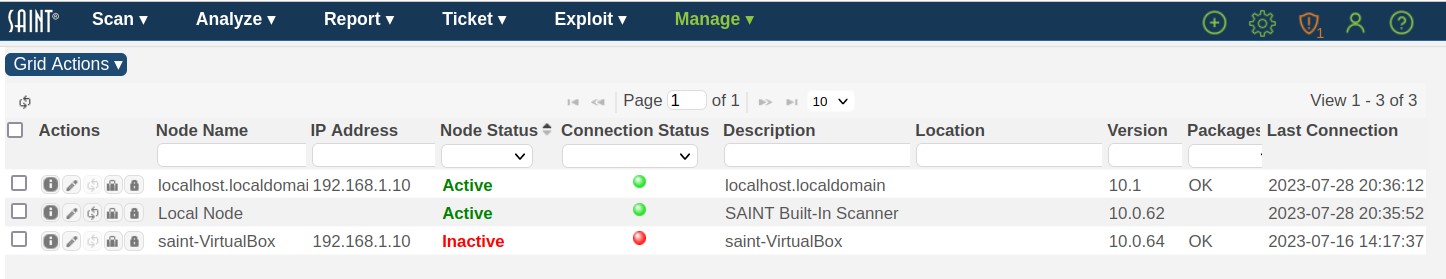
Scanner Nodes
Every installation comes bundled with at least one scanning engine, called a 'scanner node’. The default scanner node connected to the Manager, and part of the default installation, is called “Local Node”, as shown below. Scanning capability can also be extended for scanning remote locations or large-scale environments by connecting multiple scanner nodes to the manager. For example, deploying scanners inside of multiple subnets, assigning scanning permissions to groups of users to individual scanners, and enterprise-level scalability and performance by directing scan jobs across multiple scanners (e.g., load balanced scans).
The following describes the various aspects of deploying and connecting scanner nodes, and managing node information via the Node management user interface.
View Nodes
Scanner node information is provided through a grid interface to assist in tracking licensed scanners, as well as providing ease of use in sorting, searching and updating scanners as the size of your organization grows, even scaling to hundreds of distributed scanners. Note that some information can be edited to meet local needs (see Edit a Node Record), while other information is created and managed internally by the system. The following describes information generated at node connection time and managed by the system:
-
Node Name – Logical name/title for the scanner node. The default scanner node installed with all deployments is called “local node”.
-
Host Name – This value is the host name derived from the node when it receives the connection request. In many cases, this is often the IP address of the node’s host.
-
IP Address – The IP address of a non-local node; this is stored when the node is installed and configured to connect to the manager.
-
MAC Address – The MAC address of a non-local node; this is stored when the node is installed and configured to connect to the manager.
-
Node Status – By default, the local node is connected and “active” when the software is started. Additional scanners can be deployed and connected to the installation acting as the “manager,” and dynamically display whether the scanner is active (available), inactive (not available for use), busy (executing scan activity), or retired (decommissioned and no longer needed).
-
Connection Status – By default, the Local Node is connected when the system is started. Other nodes are connected at the completion of the installation and startup process, but may show a status of “disconnected” if the node is down or, stopped, being restarted, or otherwise loses a physical network connection to the manager.
-
Description – A text area to support local requirements for stating how the scanner is being used.
-
Location – A text area to help describe where the scanner is deployed. For example by country, city, state, building, floor, room, etc.
-
Node Version – The manager maintains an active record of the current version of SAINT software installed and running on each node. This information is a visual reference to ensure all scanners are up-to-date and in sync with the same software version, scanning engine updates and vulnerability check content. Scanner nodes, which have a version lower than the current manager version, have the version highlighted in red. Note that the manager version may also be out-of-date. If the manager version is not current, the top menu bar of the UI will display an “Update Available” message, as well as show this status in the Manage System Updates page.
-
Missing Packages – Each remote scan node checks its own system for package dependencies upon connecting to the manager. This text area provides information about missing packages on the node. See Package Dependencies for more information about resolving missing packages.
-
Initial Connection – The initial connection date is the datetimestamp when a node is first installed and connected. This information may be of value as node licensing needs change over time, and administrators need to track node resources over time.
-
Administrator – A SAINT user that is the primary contact that administers or manages the host or node environment.
-
Last Updated By – This datetimestamp is provided to show when node information has been updated, and is updated automatically whenever an administrator edits node information.
-
Retired Date – This is the datetimestamp generated when a scanner node is de-commissioned and no longer needed.
Installing a Distributed Node
Installing a distributed node is done in much the same manner as a typical installation. However, the start-up process provides steps to configure the installation to be run only as a scanning engine, managed by a separate installation, acting as the central manager. See the Administrator’s Guide – Start-Up Options for details on installation and setup of a distributed node.
Edit a Node Record
Editing node information via the node grid is supported by two methods:
1) In-line field editing by clicking in an editable field
2) Clicking on the edit icon (pencil) on a node record to display an edit node dialog window.
The following fields are editable through these methods:
-
Node Name – The default value for the built-in scanner node is “local node.” This value, as well as other connected node names, can be edited to help uniquely identify the scanner.
-
Administrator – This is an optional field to assist in tracking the staff member's, team, organization, etc. that is accountable for administration of the node.
-
Description – This is an optional text field for adding additional information about the node. For example, to describe the purpose or intended target environment a scanner node is connected to.
-
Location – This optional text field is for describing where a node is installed.
Restarting and Updating
When software updates are available, the remote/distributed (non-local) scanner nodes should be restarted in order to obtain those updates. You can restart an individual node by selecting the Restart Scannode icon ( ), or select multiple nodes via the checkboxes, then choose Restart Selected Scanner Nodes from the Grid Actions dropdown menu. The Restart Scannernode permission is assigned on a per-node basis.
IMPORTANT – Restarting the local node also restarts the manager. As a result, granting a user permission to restart the local node also grants permission for the user to restart the manager as well.
Package Dependencies
When SAINT is first installed, either as a manager or a node, it checks that all of the software packages required for running SAINT are installed on the system. However, new package dependencies may arise over time as new functionality is added to the product. If one or more remote scanner nodes are missing packages, an alert is shown in the header bar of the web interface, and the scanner nodes with missing packages are indicated with a red background in the Missing Packages column of the scan nodes grid.
When a remote scanner node has missing packages, there are three ways to resolve them:
-
Single node package resolution: Click on the Packages button (suitcase icon) for the desired scanner node on the scan nodes grid. This action button will open a dialog indicating which packages are missing on the node. In that dialog, click on the Install Packages button to install the missing packages, and wait for a response.
-
Bulk package resolution: Check the box for every desired scanner node or check the box on the grid’s header bar to select all scanner nodes at once. Then choose Install Packages on Scanner Nodes from the Grid Actions menu. The grid will then be updated periodically as the missing packages are resolved. This is the best option if many nodes have missing packages.
-
Command-line package resolution: Log into a command shell on each remote scanner node and run the following commands:
cd /usr/share/saint
sudo scripts/check_deps8.
This will give you a more interactive experience, allowing you to see what is being installed and confirm each step of the installation.
Note that the package dependencies on the local node do not need to be managed as described above, since the local node is part of the manager. Package dependencies for the manager can be checked and resolved on the System Status page.
Configure System Updates
-
System updates process – (aka SAINTexpress process) provides configuration and control over the process of checking for and obtaining updates from the SAINT update server whenever the product starts. Select the System Updates menu option to display the current configuration, including the required user name, transmission password and transmission key. Refer to the Administrator’s Guide for more information about setting up and managing the update process.
-
Restart and update the system – The manual restart process can be optimal for obtaining the latest checks, exploits, and tutorial content immediately whenever updates are available, or to ensure all system updates are in place prior to a mission critical scan such as risk or compliance reporting.
-
Manual updates – This process is vital for organizations that have off-line environments that cannot be configured to obtain updates via an Internet connection. Users can obtain update files from the mySAINT customer portal from an Internet-connected environment. That file can then be used from the off-line installation to execute updates to ensure the scanning solution remains up-to-date with the latest capabilities and content.
Configure License Key
When installing Security Suite for the first time, one of the first steps is to generate a license key and configure the key in the product. This process also automatically adds the necessary credentials to configure the key credentials, and configures the update process for auto-updates. The License Key page displays the form where you can enter your key into the text box, and displays the current status of your key once it is in place. If you do not already have a key, refer to the Administrator’s Guide’s section on How to Obtain a key.
Note that this process does require Administrator permissions, as well as the Account credentials provided by SAINT when your account was created.
System Maintenance
System maintenance features are found by selecting the Manage tab's System Maintenance option. These features enable administrators to perform such actions as data backup/archiving; viewing various system logs; facilitating lower level troubleshooting with SAINT’s technical support by enabling debugging to support additional error handling and messaging; transmitting logs and content securely to support, if needed; and viewing system messages directly through the user interface. Each of these features is described in more detail below.
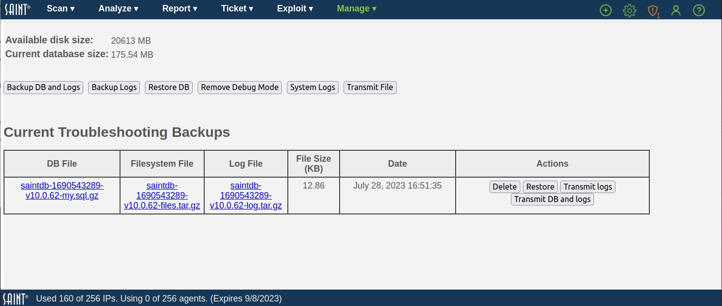
Backup Database and Logs
The backup DB and logs feature provides one-click support for creating a dump file of the current database, any files referenced by the database, and all scan and system log files and relevant operating system information. A list of prior backups is displayed in the table (as shown above). This capability serves two primary purposes:
1) enables you to store periodic snapshots of your database for archiving in the event of a system failure, or use in an external system
2) provides a quick mechanism to create a snapshot of the database in the event you are working with the support team on an issue that requires investigation of the data results.
There is also an option to backup just the log files and operating system information without the database, which may be helpful if the database is very large.
Note: Only the admin user and members of the Administrators group can download the backup files.
Restore
The backup files described in the previous section can be used to restore the SAINT database to the state it was in when the backup was taken. This may be useful in the event of data corruption, accidental deletion of data, or migration to a new platform.
There are two ways to restore the SAINT database from backups:
-
Click on the Restore button on the desired row of the backups table. This method is useful for restoring the system to a previous backup point on the same system.
-
Click on the Restore DB button at the top of the page. This method is useful for restoring the system onto a new platform. Clicking on this button opens a dialog which prompts you to upload two files. The first should be a gzipped SQL command file downloaded from the DB File column of the backup table, with a filename ending in .sql.gz. The second file should be the gzipped TAR file downloaded from the Filesystem File column on the same row of the backup table.
Regardless of which method is chosen, a browser dialog will warn you that restoring the database will entirely delete the current database and confirm that you want to proceed. Then a dialog will inform you that the system needs to be restarted. Click the button to restart the system. It may then take anywhere from a minute to several hours for the system to come back up, since this is when the restoration is taking place. If the restoration fails, the system will usually come up unchanged, depending on where the failure occurred. You can then see the reason for the failure in the manager logs. (See System Logs.) If the restoration succeeds, SAINT will automatically download the database update files needed to make the database schema and static data compatible with the installed software version.
Note: only the admin user and users in the Administrators group may use the restore function.
Delete
Click the Delete button in a row of the backups table to delete the files listed in that row.
Transmit Files to Support
Each row of the backup table provides buttons to transmit the files to the SAINT support team. There is also a Transmit File button at the top of the page which allows you to transmit any file from the manager’s file system. These functions may help the support team resolve your support tickets faster. Please use these functions only if instructed by the SAINT support team.
Restart in Debug Mode
Restarting Security Suite in Debug Mode should only be done upon request from the SAINT support team. This action restarts the manager and turns on debugging/logging actions to capture detailed information about potential system problems that standard logging does not capture. This step is typically requested and monitored when in contact with a support engineer, and is used while reproducing the actions and steps previously taken that resulted in a problem. Once these actions have been completed, the support team will request that you restart the product again, without debugging turned on, by clicking on the Remote Debug Mode button displayed while the system is running with debug enabled.
System Logs
This system maintenance feature provides a tool for monitoring the health of the system and troubleshooting issues when they arise. Note that his log information does not automatically constitute system problems or errors in the execution of scans, analysis or reporting. This information may contain a variety of administrative events, regardless of the source. Please provide the messages in this log to SAINT Technical Support, upon request.
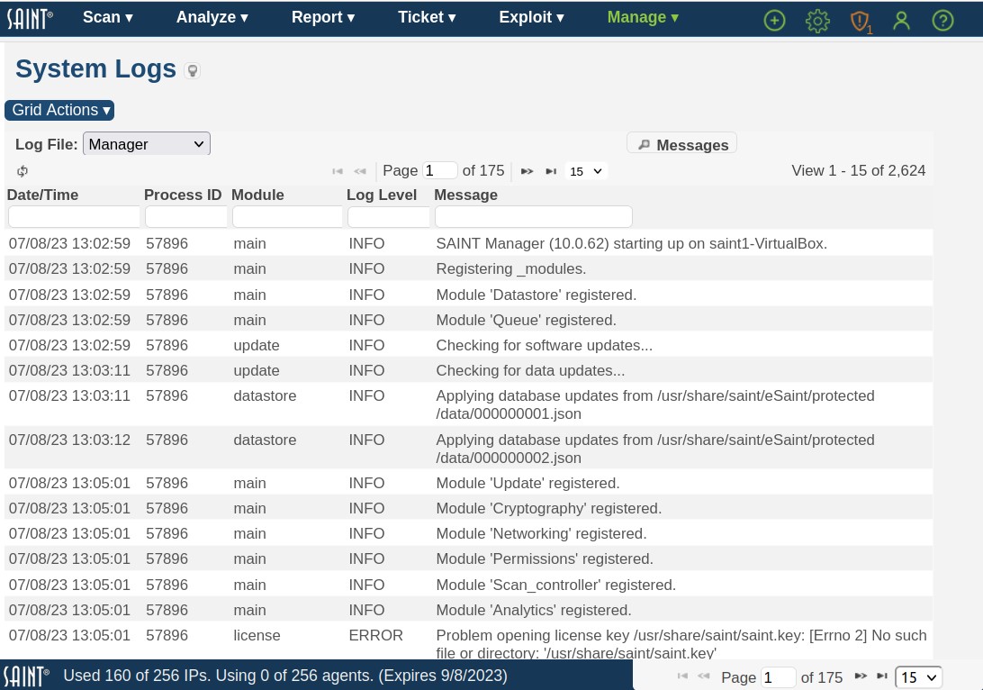
As shown above, the System Logs are broken out into seven different types, each available in the dropdown list at the top left of the grid:
-
Manager – messages produced by the main manager service, including messages related to manager startup and shutdown, connections from nodes, and scan job processing.
-
Scanner – messages produced by the scanner agent, including messages related to agent startup and shutdown, connection attempts to the manager, and scan activity.
-
Agent – includes logs produced by manager including related to SAINTAgents Management service, startup and shutdown, connection attempts to the agent and other related activities.
-
Web Server – log of HTTP requests received by the web server process, and the corresponding responses. (The verbose option controls how much information is logged.)
-
Application – messages produced by the web application, such as PHP exceptions and warnings.
-
User – log of user activity, including logins, password changes, object permission changes, and creation or deletion of users, groups, and scan jobs.
-
SAINTexpress – log of software update requests and actions.
-
Email – e-mail messages sent from the software, including scan completion notifications, scan reports, ticket assignment notifications and ticket reminders.
Messages
This capability also provides a quick message search button to display internal system messages, separate from the various logs. As with the log messages, content in this view does not always constitute an error or problem with the operations of the software. However, like the log content, can be a useful tool for the support team to review when investigating an issue.
System Status
The System Status provides an overall summary of the state of the system, from product version number, to the current license information, status of the automated update process (SAINTexpress) and an active status of activity; as well as additional options applicable to system management, such as restarting the system or scan daemon to accept system-level configuration changes.
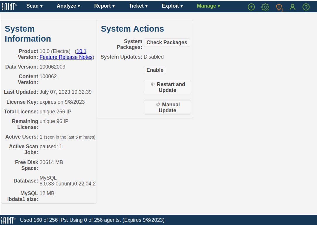
The admin user can use this page to quickly see the state of the application, such as the product version number, licensing information and key expiration date.
System Information
This section provides current information about the installation, such as product and content version, license information and status, date of the latest updates, and activity on the system (active users and active jobs). This information can be important for troubleshooting issues as well as determining what will be affected by performing actions such as restarting the system and updating the system as a result of global configuration changes or getting the latest vulnerability checks, exploits and content from SAINT.
System Actions
The System Actions section provides options for checking and validating the status of system dependencies; one-click toggle button to change enable or disable the automated update process; and shortcuts to obtaining system updates or performing manual updates.